Products
- Card Edge Connectors
- RECTANGULAR CONNECTORS
- D-Sub Connectors
- Machined D-Sub Connectors
- Power Combo D-Sub Connectors
- Parallel Port D-Sub Connectors
- Waterproof D-Sub Connectors
- DB9 Connector
- DB15 Connector
- DB25 Connector
- Vertical PCB D-Sub Connector
- D-Sub Panel Cut-outs
- Cable Wire D-Sub Connector
- PCB D-Sub Connector
- Right-angle PCB D-Sub Connector
- Backshells or Hoods, and Caps for D-Sub Connectors
- D-Sub Connector Housings
- D-Sub Connector Contacts
- Modular & Magnetic Jacks
- USB Connectors
- HDMI Connectors
- INLINE CONNECTORS
- HEADER CONNECTORS
- Spring Loaded Connectors
- Waterproof Connectors
- Cable Assemblies
- Custom Connectors
Ruggedized Connectors for Applications within Harsh Environments
Applications such as industrial, military/defense, aerospace, public safety, and transportation will often require a level of ruggedization for all the connectors used within their systems. Cable assemblies form the backbone of the electronic systems, granting the necessary data and power connections between internal circuits/PCBs, equipment, and peripherals. Many of these harsh-environment applications will rely on standard commercial physical interfaces and protocols for data and power transfer, this includes HDMI, USB, and ethernet. Other common connectors that require ruggedization are D-subminiature (D-sub) connectors often used for serial communications. The examples of connector types used in rugged applications are endless and can range from wire-to-wire, wire-to-board, board-to-board, to larger connectors (e.g., coax, circular) that connect to and from equipment (e.g., sensor nodes, avionics, controller, gateways, measurement devices).
This article delves into the various engineering considerations for connectors used within rugged applications and how these connectors can continue to operate with mechanical, environmental, and electrical strains.
Rugged application trends: Shifting from proprietary to off-the-shelf protocols and connectors
There’s a broad range of applications that expose electronics to environmentally, mechanically, and electromagnetically unstable settings. Industrial applications encompass some of the harshest environments for electronics and their connectors, these applications include process automation, oil and gas, mining, food and beverage, waste management, water treatment, pharmaceuticals, textile, and agricultural facilities. Many industrial facilities are shifting from costly proprietary solutions (e.g., proprietary OS and fieldbus technologies) to solutions that are more available in the commercial marketplace. Many facilities, for instance, have already adopted industrial ethernet (IE) over traditional fieldbus technologies for the industrial automation architecture due to the accessibility of the ethernet standard. Industrial controllers and PLCs are also increasingly using open OS. Naturally, the conventional random access ethernet protocol has been adopted for more predictive data delivery within modified ethernet standards such as EtherNet/IP, PROFINET, EtherCAT, and Modbus. Similar to the modifications made to the IE protocol for more reliability, ethernet connectors themselves must also be ruggedized for reliability in harsh industrial environments.
Other rugged electronics applications such as military systems are also seeing a shift to leveraging commercial off-the-shelf (COTS) components wherever possible. Military agencies such as the Department of Defense (DoD) and NASA will contract out engineering and technical support (e.g, ground-based vehicle, aircraft, avionics, military radio, missile defense systems, ISR systems) related to research and development efforts [1]. However, this type of spending (involving long, drawn-out contracts) has been deemed inefficient by the Government Accountability Office (GAO), at which the DoD was on its “high-risk list” since 1995.
Processes such as the lowest price technically acceptable (LPTA) have been implemented as an effort to modernize these business systems. For engineering components such as connectors, this often translates to these agencies scanning the commercial marketplace for high-reliability components set at a reasonable price. The DoD could ascertain additional information — such as lot traceability, part acquisitions, and a test report for quality assurance — to vet both the vendor and the product. Additional modifications could be made to parts for, for instance, explosion-proofing a commercial navigation system [2]. This means that COTS components can meet mission requirements and make their way into military-grade systems as they shed the R&D costs and guarantee a quicker time to deployment.
This trend can also be seen in transportation applications such as marine, heavy equipment, railway systems, and commercial aircraft (e.g., airliners, eVTOLs). For example, the avionics full-duplex switched ethernet (AFDX) architecture, or ARINC 664 Part 7, is an avionics communications protocol that is based on the ethernet protocol to offer secure, high-bandwidth communications to avionics. This is now commonly used in commercial airliners as a shift from the older, point-to-point communications found in MIL-STD-1553B and ARINC 429. Commercially available connectors and cable assemblies that are ruggedized often fit the bill when it comes to implementing them in a solution meant for these relatively harsh environments.
Ruggedizing common commercial connectors
This trend of commercial protocols and interfaces being used in more niche, harsh environment systems calls for ruggedized solutions for common connector configurations including but not limited to: ethernet, USB, HDMI, and D-sub. The HDMI connector is often used for an industrial or military human-machine interface (HMI) used in outdoor environments (e.g., within heavy equipment machinery, for monitoring/control of an outdoor-based system). D-sub connectors are often used for RS-232 and RS-485 serial communications connecting a computer to various peripherals such as a modem or a printer. In other cases, these connectors are used in heavy-duty vehicles (Figure 1) and even in industrial applications, outfitted with both power and signal pins to carry various industry-specific protocols (e.g., CAN/CANOpen, CC-Link, ControlNet, DeviceNet, M-Bus, Modbus RTU, PROFIBUS).

Figure 1: An Anybus industrial gateway that provides connectivity between a PROFIBUS network and a heavy-duty vehicle (CAN) network with a D-sub 9-pin female connector. Source: Anybus
Other common wire-to-wire, wire-to-panel, wire-to-board connectors can be used as well, including rectangular, coax, card-edge, inline, and more. Multi-board systems use card-edge connectors in backplanes, for instance, as expansion cards in PCs, in industrial control systems between PLCs and sensors, and actuators. While there is a great deal of vendor diversity for many of these connectors, not all manufacturers will offer a ruggedized solution. Rectangular connectors are critical in rack and panel applications for signal connections between large pieces of equipment. Oil and gas refineries will, for example, need a very reliable, high-continuity connection for the safety of their employees and the systems they operate. These systems can include pressure transducers and temperature sensors that feed through data loggers that, in turn, connect back to computers. The rack and panel connectors ensure those signals are unimpeded and without distortion, increasing the accuracy of the results.
Most commercially available connectors will fail prematurely in a harsher environment. The types of connectors deployed within these systems vary tremendously and the real requirements generally boil down to protection against dust/moisture ingress, vibration, shock and thermal shock resistance, and EMC/EMI testing. This is a task in and of itself ― connectors will often fail prematurely and suffer from intermittent connections with long-term exposure to these stressors.
Environmental Requirements
Connector failure modes related to environmental strain
Some examples of environmental stressors are dust/moisture ingress, humidity, thermal shock, UV exposure, and chemical hazards. When subjected to these stressors, standard connectors would likely fail. Contamination from humidity and/or moisture, for example, could create corrosion within the connector, which could cause poor contact reliability and an intermittent connection. This can lead to eventual connector failure. Contaminants such as dust and oil can create an insulating barrier which can greatly impact the quality of the connector mate on some or all of the mating surfaces.
Temperature-related strain can also occur, which can, in some cases, impact the connector. Firstly, the materials used within the connector housing as well as the cable may not be rated for certain temperatures — e.g., the plasticizers used in many thermoplastics found in connector/cable jackets can migrate at high temperatures (as well as with exposure to UV and chemicals) which will cause melting, cracking, splitting, and brittleness, ultimately leading to a premature failure. Sudden and rapid changes in temperature can cause a material breakdown that leads to a decrease in dielectric strength ― a parameter that can affect the electrical performance of the connector.
Another consideration is the various coefficients of thermal expansion (CTE) for the materials used within the connector: These materials will expand/contract at different rates, potentially causing both mechanical and electrical issues for the connector/cable. This is especially critical for high-speed connections where the interfaces right up to and at the point of connection must remain uniform and without contamination. High-frequency signals, for example, will see a mismatch from one connector head to another, causing reflections and more signal loss (high attenuation). Ultimately, thermal shock can cause thermomechanical failures, mechanical deformation, increased contact resistance, increase the rate of chemical reactions at interfaces, insulation breakdown, and electromigration [3].
Environmental requirements for connectors
The electronics within these applications will often require protection from both water and dust ingress with an ingress protection rating (IP rating) as per IEC60529. The International Protection Marking (IP code) system uses two digits after the letters IP to indicate the level of protection against dust and moisture. A system can either be protected from an object greater than 50 mm (IP1x) or completely dust tight (IP6x). In terms of moisture protection, the system can be protected against vertically falling drops of water (IPx1) or be protected against complete immersion (IPx7 or IPx8).
EDAC offers dust- and waterproof HDMI, USB, in-line, and D-sub connectors with an IP67 rating (Figure 2). This is possible through the E-seal technology that uses an epoxy-sealing process which manages to seal the entire back of the connector rather than at individual pins. This method ensures a complete seal with an immaculately smooth finish, and guarantees no water ingress, as fully tested to IP67 standards. In wire-to-panel applications, an additional o-ring reliably seals the connector shell to the panel. EDAC’s rectangular connectors can have optional plastic or metal covers that provide basic dust/debris protection.
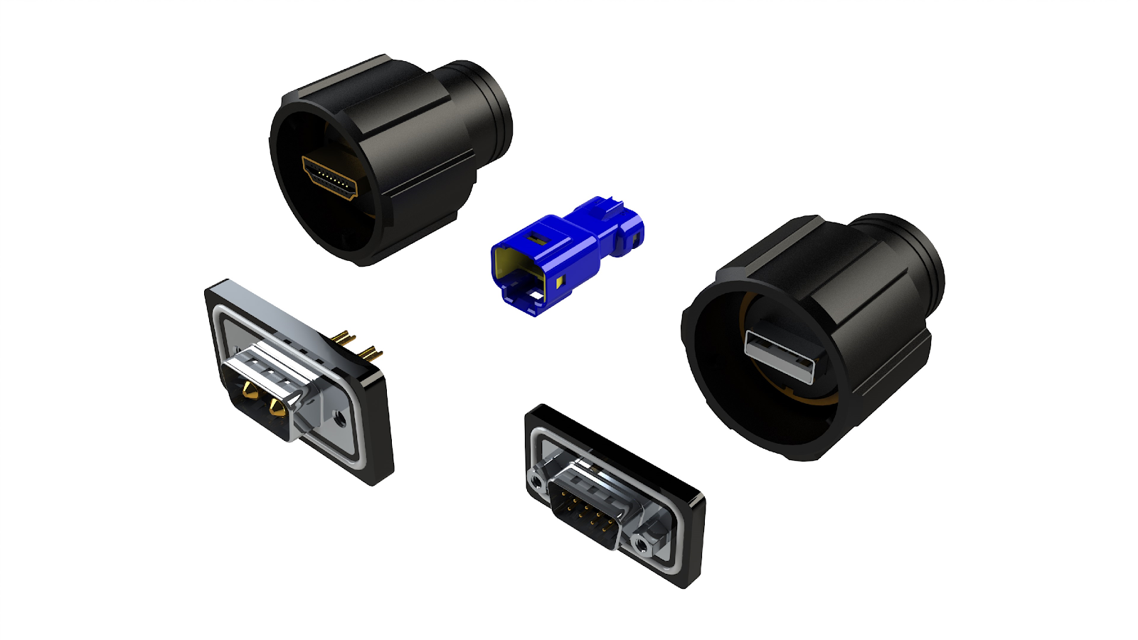
Figure 2: IP67-rated connectors offered through EDAC.
Another engineering consideration for protection from contaminants and moisture that cause corrosion is the customizability of plating thickness. While gold itself is corrosion resistant, at the microscopic level the malleable metal is quite porous. This can cause contaminants to slip through the cracks and react with the materials underneath the plating, corroding, and forming an oxide layer that will negatively impact the conductivity and continuity of the connection. EDAC’s card-edge connectors offer up to 30µ'' gold plating on the mating area for card-edge, rectangular, and D-sub connectors. This is a moderate amount of plating and can greatly improve corrosion resistance in harsh environments over conventional flash plating.
Connector heads can utilize high-temperature materials in order to mitigate the damage caused from thermal shock. For instance, EDAC’s high-temperature card-edge connectors utilize high-temp insulators (i.e., Diallyl Phthalate or Polyphenylene Sulfide), allowing them to perform in a wide temperature range from -40° C to +125° C. The EDAC D-sub connectors also function in a wide temperature range from -55° C to +125° C through the use of carefully chosen materials.
Mechanical Requirements
Connector failure modes related to mechanical strain
Typical mechanical strains to connectors include shock, vibration, and mating cycles. Vibrations are technically defined as mechanical oscillations of an object about an equilibrium point. These can occur intermittently from wind or continuously from equipment such as speakers, solenoids, and motor-based equipment (e.g, fans, conveyor belt, pumps, robots). Vibration can loosen a connector’s contact pins or the mate between pins and sockets, causing an unreliable or intermittent connection.
Another common failure mechanism with vibration is fretting corrosion or the erosion of the metal surfaces due to repeated rubbing — the sliding motion between surfaces can vary from microns to millimeters. This causes mechanical wear such as pitting as well as material transfer to the surface of the other material, leading to corrosion at the freshly exposed metal interface. Once this occurs, the rate of fretting and mechanical wear drastically increases, causing potential failure [4]. For a similar reason, extensive mating cycles, or the repeated mating/unmating of the connector, can cause a failure. The continued abrasion to the mating surfaces can cause corrosion to increase. Mechanical shock is a sudden acceleration or deceleration to an object from an impact, drop, crush, kick, or even an explosion. A severe enough shock can cause mechanical deformation to the connector housing and the connected pins within the mate.
Mechanical requirements for connectors
The effects of these stressors can be minimized with a carefully designed and precision mate between pins within the connectors. EDAC’s EDACON hermaphroditic contacts (Figure 3) use a fork-like design that incorporates four mating surfaces. When mated, the contacts align at 90° to one another and provide four points of contact, creating an extremely high-continuity, gas-tight connection. The contacts have beveled edges that float in the insulator; this float allows for some movement of the contacts to help with mating/unmating as well as vibrations. Both EDAC’s card-edge and rectangular connectors utilize this topology for a high resistance to vibration and mechanical shock. Rectangular connectors tested according to the MIL-C-28731 military standard are also available. This connector specifies requirements and tests for rectangular connectors intended for use in airborne, ground support, and shipboard electrical and electronic equipment.
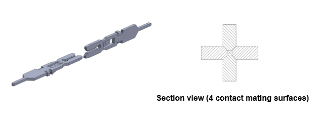
Figure 3: EDAC’s EDACON hermaphroditic contact provides a gas-tight seal (left), a cross-section of this connection will reveal beveled edges that allow for mechanical movement such as mating and vibration (right).
Contact pins with a higher plating thickness will allow for more wear resistance as there is a greater surplus of plating material to scrape off with every sliding/lateral motion. As stated earlier, this can also be customized with specific EDAC connectors, decreasing the risk of common failure modes that come with vibration, shock, and frequent mates. The EDAC USB and HDMI connectors do not have individual pins as the rectangular and card-edge connectors do. However, they offer a bayonet-styled mate which cannot be easily unmated or loosened in the event of excessive vibrations or shock.
Electrical Requirements
Connector failure modes related to EMI
Wireless devices are now more prolific, potentially causing unwanted interference. However, unwanted EMI can also radiate from devices that are not necessarily wireless. This is especially the case in industrial environments where uninterruptible power supplies (UPS), motors, transformers, and switching power supplies can radiate unwanted noise due to the generation of non-sinusoidal waveforms that create third-order (and beyond) harmonics.
Radiated emissions are unwanted noise that “radiates” or escapes from equipment and travels in air. Conducted emissions, on the other hand, require physical contact, and this form of interference is transferred via conductors such as connectors or cables. Oftentimes, equipment will fail emissions testing due to its cabling. A cable assembly can act as an antenna, causing them to both conduct and radiate emissions. In order to minimize the risk of equipment going out of compliance due to attached cabling, it is important to properly terminate the cable with the connector, use shielded cables over unshielded cables, use connectors with metal shells/covers, and ground the shield in both the connector and cable to chassis ground.
Electrical requirements for connectors
EDAC’s D-sub connectors will come with metal shells to provide EMI and RFI shielding; the plug shell indents (as shown in Figure 4) provide additional ground as well as mating retention. The rectangular connectors also come with optional metal covers to provide another level of EMI protection.
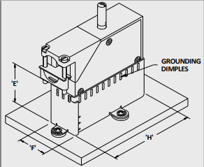
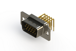
Figure 4: EDAC D-sub connectors have a metal shell as well as indents that will provide additional grounding (left), while rectangular rack and panel connectors come with an optional metal shell and grounding dimples to provide an additional layer of EMI protection.
Conclusion
Many electronic components and their connections are subjected to harsh mechanical, environmental, and electromagnetic stresses in rugged applications. There are many failure mechanisms that can occur if these connectors are not adequately protected against these various strains. An engineer looking for connectors in these environments will often have to consider this and ensure the component deployed will not prematurely fail in the field or radiate unwanted emissions.
The potential risk of either an intermittent connection or an outright failure can range from potentially catastrophic (e.g., loss of life) in mission-critical applications such as public safety, military, or functional safety systems on the plant floor, to unwanted downtime in an industrial facility. While the latter is not as severe, a poor choice of connector can cost an operation a great deal in terms of opportunity cost and costs to troubleshoot/repair. To limit these issues, it is important to understand the stressors a connector might endure relative to its use case and adequately protect against it. EDAC offers a massive range of off-the-shelf connectors that have been ruggedized to fit many of these end-applications. EDAC’s legacy with connectors spans decades, allowing the company to build diversity within the connector ecosystem as well as competent engineering support/expertise.
References
- “Contracting Data Analysis, Assessment of Government-wide Trends,” GAO-17-244SP, March 2017, www.gao.gov/assets/690/683273.pdf.
- “Improved Information Sharing Could Help DOD Determine Whether Items Are Commercial and Reasonably Priced,” GAO-18-530, July 2018, www.gao.gov/assets/700/693919.pdf.
- Martin, Perry L., et al. Electronic Failure Analysis Handbook. McGraw Hill Professional Publishing, 1999.
- Yoshiki Oshida, 5 - Mechanical and Tribological Behaviors, Bioscience and Bioengineering of Titanium Materials (Second Edition), Elsevier, 2013, Pages 117-137, ISBN 9780444626257.
Go Back