
CONNECTORS FOR ROBOTIC APPLICATIONS (ENGINEERING CONSIDERATIONS)
From automated guided vehicles (AGVs) and autonomous mobile robots (AMRs) to six-axis robots, robots are used to accomplish mechanical tasks with precision. Applications for these machines vary from military and industrial automation to consumer and medical. The permeation of AI made its way to robots rapidly, to train and automate this equipment for their respective tasks — sometimes with human intervention, other times with minimal human intervention.
Robots are complex multimodal systems that incorporate mechanical, pneumatic, hydraulic, and electrical principles. This means that the circuits, cables, and connectors within robots will undergo vibrational strain and tensile forces that can cause connectors and cabling to fail. Other types of stressors can include thermal shock and exposure to harsh chemicals and contaminants such as dust and oil. This article describes the engineering considerations of connectors used in robotics.
Different types of robots
Possibly the most classic example of robots is robotic manipulators, such as robotic arms used in industrial automation to move and assemble parts of large equipment such as automobiles (Figure 1). While this is a common type of robot used in modern manufacturing applications, there are many other robots as well.

Figure 1: The KUKA robotic manipulators performing spot welding for automotive assembly. Source: Wikipedia
The AMRs and AGVs mentioned earlier, for example, will create real-time 3D maps of their environment using algorithms such as simultaneous location and mapping (SLAM). As shown in Figure 2, this can simplify asset management or the movement of assets within a facility. The difference between these two robots is that AMRs will traverse their environment freely using lasers, 3D cameras, and ultrasonic sensors, while AGVs, as their name implies, are guided by a predefined path with elements such as magnetic tapes, magnets, and beacons.
Sensor systems and their interconnections ensure the smooth operation of these robots and are critical to their functionality. Sensor modules often come with unique environment strains that will have to be considered when choosing connectors and cables. To learn more about the various issues that are faced by sensor systems, read “Engineering Connector Considerations for Sensor Applications.”
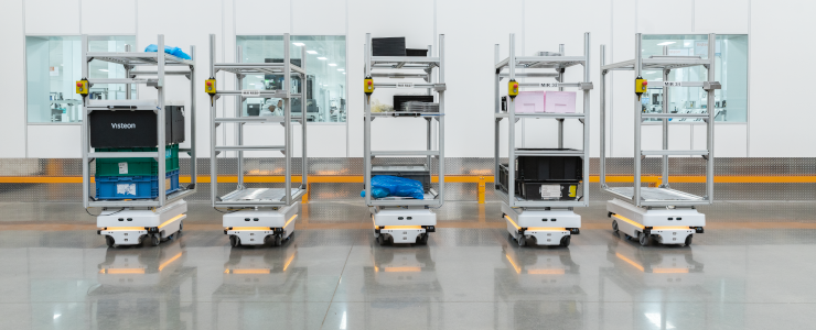
Figure 2: The MiR100 AMR from Mobile Industrial Robots (MiR) transporting raw materials from a warehouse to the production lines and returning finished products. Source: MiR
There are also humanoid robots that will replicate the human appearance. These are mainly used for education, entertainment, and personal assistance within various industries from research and space exploration, search and rescue, medical, agriculture, and more. Collaborative robots, or cobots, are another subset of popular robots that are meant to work in tandem with a human to accomplish a specific task. For instance, in agricultural applications to identify flowers and fruits for more efficient pollination (Singrow cobot). Other examples of cobots include assisting with the welding of various machines in industrial spaces, cleaning in living spaces, and packaging, palletizing, and lifting in smart factories. Note many examples of cobots can also be considered AMRs. These hybrids combine the functionality and utility of multiple types of robots to optimize the efficiency of performing a specific task or to open up the number of tasks a singular robot can accomplish.
Medical robots will use several telemanipulators that can be remotely operated by a surgeon using haptic feedback and, in some instances, voice activation (Figure 3). This naturally comes with the assistance of AI and machine learning algorithms.
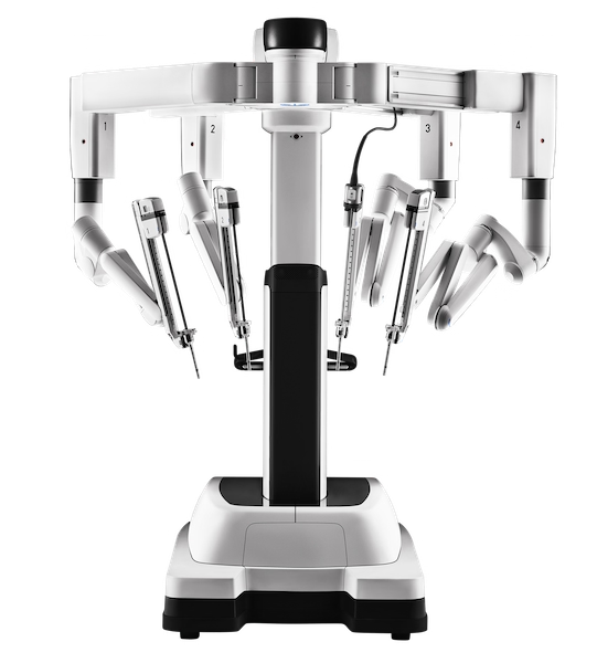
Figure 3: The Da Vinci Xi surgical system. Source: Intuitive Surgical
Electrical Signals Used Within Robots
AMRs and AGVs
Robots are complex machines capable of carrying out varying tasks with a high degree of precision. This involves tight coordination between mechanical, pneumatic, hydraulic, and electrical systems as well as the rapid processing and response to any feedback. Robots rely on sensor data to measure and calculate distances to and from objects to, for example, lift or avoid. This also requires power and data signals to and from motors and actuators. A flow diagram for the navigation performed in an AMR can be seen in Figure 4.
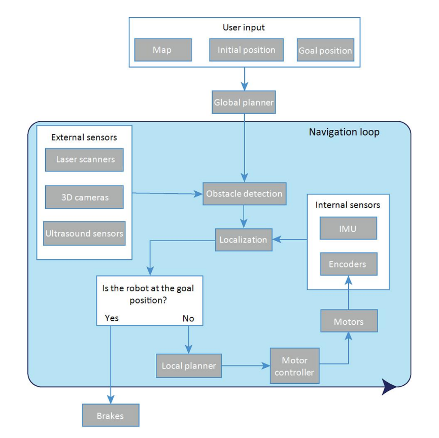
Figure 4: Flow diagram of the navigation for the MiR AMR where the user provides the map, initial position, and goal position, while the “global planner” of the AMR executes the rest of the steps in the navigation loop until it reaches the goal position. Source: MiR [1]
As shown above, external sensors are used for obstacle detection and will coordinate with the robot’s internal processing, including the local planner, motor controllers, motors, and internal sensors such as encoders and an inertial measurement unit (IMU) for free movement within an environment until the end position is reached. The communications interfaces can and will depend upon the type of unit used to process data (e.g., fpga, MCU, industrial-grade embedded platforms, SBCs). Many of these will use COM ports such as RS232 for communications with the various instrumentations within the AMR or AGV (Figure 5).
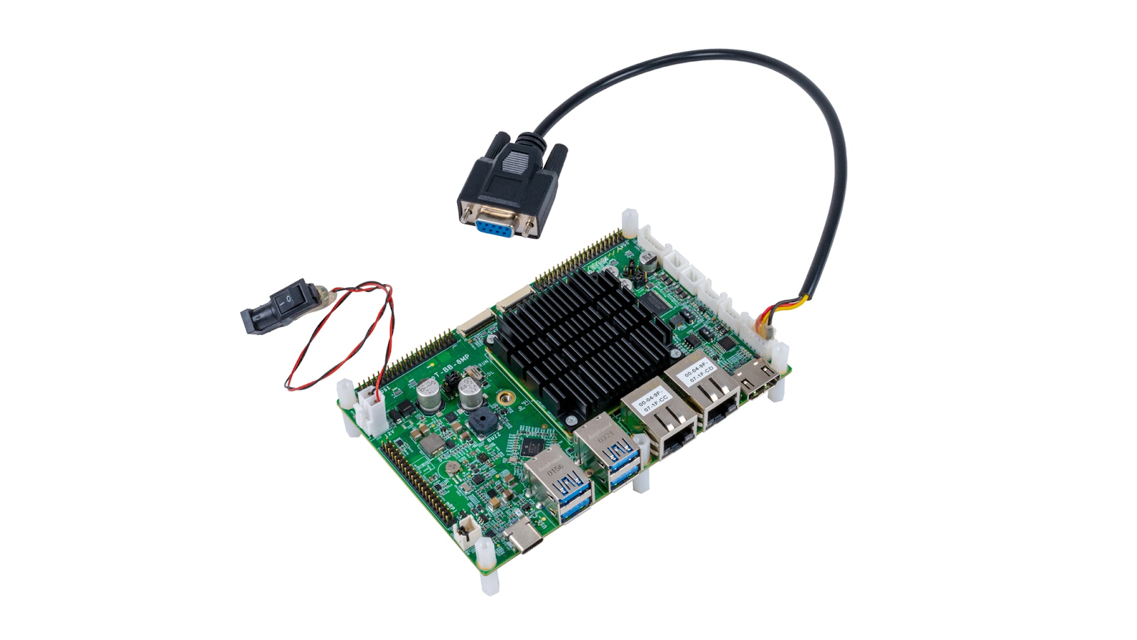
Figure 5: NXP’s AI robot platform with a CANFD port, a MIPI-CSI port for a camera connection, RS485 port, and five USB 3.0 ports. Source: NXP
As shown in Figure 6, ruggedized, brushed DC motor controllers will also often include RS232, RS485, USB, and ethernet ports.
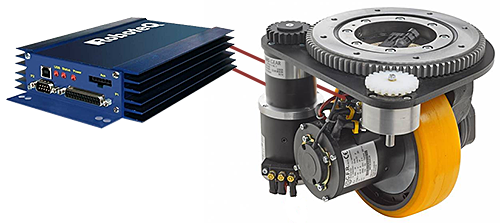
Figure 6: Brushed DC motor controllers from RoboteQ. Source: RoboteQ
Robotic manipulators
Most robotic manipulators are made up of six or more degrees of freedom (DOF) for complete control of the position and orientation of the end-effector — the device on the end of the robotic arm that is meant to interact with the environment. This part is meant to be attached to the robot’s “wrist” to adjust the end-effector’s hand orientations while the robotic “elbow,” “shoulder,” and “base” can adjust the position of the end-effector in space (Figure 7). All these parts include servos for precision control of each section of the robot.
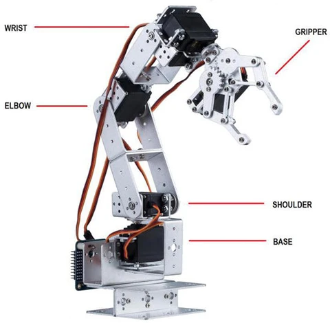
Figure 7: The parts of a robotic arm. Source: [2]
All servos and tools in the end-effector will require power and signal for operation. Rugged connectors are typically used for these applications. Electrical cabling must also be smartly designed, ideally within conduits along (or through) the links of the manipulator [3].
Mechanical Requirements for Robotic Connectors
It is a fact that many cables used within robotic manipulators will endure millions of bending cycles (linear stress) as well as torsional strain and tensile forces that can cause tangled or corkscrewed cables. Oftentimes, cable carriers are used that act similarly to corrugated tubing that have limited bending and twisting capabilities to reduce the stress to internal cables by ensuring they are not flexed beyond their rated bend radius. These mechanical stressors not only impact that cable but the connector as well. Connector heads that offer strain relief are imperative, and high-retention strength connections ensure tensile forces and vibrations will not cause the connector to dislodge or entirely disconnect. Connector heads must have a solid locking mechanism such as quarter-turn twists to hold the mate during the operational lifetime of the device.
Environmental Requirements for Robotic Connectors
High-temperature strain
The prevalence of robots in such a wide range of industries inevitably results in some robots facing truly harsh environmental conditions. One severe example is the “Extreme Temperature Drill System” that is designed to be able to drill the surface of Venus by functioning more than 20 hours at 460o C (860o F) [4]. Most environments won’t be so brutal, but this does highlight the great variety of use cases. Some robots must withstand sub-zero temperatures, high altitudes, and thermal extremes ― all of which bring their own respective engineering considerations. Other examples of high temperatures and harsh environments are fully automated robotic welding or furnace tapping or the act of digging out the plug used for stopping molten metal from coming out of a blast furnace (Figure 8).

Figure 8: The MIRS automated, heavy-duty, ceiling-mounted furnace-tapping robot with exchangeable drill tools and plugging tools (e.g., mud gun), equipped with a heat-resistance suit. Source: [8]
All materials used within a connector will experience a different coefficient of thermal expansion (CTE) that can potentially cause deformations and irreversible changes in material properties such as dielectric strength and elasticity. While a breakdown in the insulating materials might be OK in the short term for some connectors, for connectors that carry signals that have relatively high power or high frequency, this will cause a major drop in performance. Many connectors carrying high-frequency signals rely on the symmetry of their cable and connector, and deformations that change the cross-sectional uniformity on points of the signal-carrying cable/connector will cause signal reflections and unwanted attenuation. For high-power signals, any breakdown in dielectric strength can cause arcing and signal shorting, or failure. For a connector to withstand these high temperatures, it is important to incorporate high-temperature materials. EDAC does this, for instance, with their high-temperature card-edge connectors by using Diallyl Phthalate or Polyphenylene Sulfide insulators.
It is also important to consider that connectors will derate — in other words, the connector pins will not be able to carry the same amount of current through them as they would have otherwise. This will need to be considered and compensated for when designing a connector for hot environments.
Dust and oil ingress
In general, it is best to keep all electrical connections free from any contaminants. However, some environments bring many opportunities for dust, moisture, or oil/chemical ingress (Figure 9). This is especially true for robotics. Dust and oil are insulators that will degrade the quality of the electrical connection. If this ingress has reached the contact pins, it will place an insulating material between what was meant to be a conductive pathway between the often-gold-plated connector pins. An additional consideration with chemicals and oils exposure is that these fluids may carry agents that will cause corrosion and the degradation of the connector’s internal polymers and/or metals. Oils can break down plastics and chemicals (e.g., insecticide solutions, crude oils, ammonia) and cause corrosion. If these fluids have permeated into the connector and are not cleaned out thoroughly in a timely fashion, the problem will accelerate and cause a total failure in the connector. To avoid this, it is important to use connectors that are dust-tight and waterproof. This ensures a high-integrity mate where all the contact pins are safe from any potential contaminants that could degrade the connection.

Figure 9: The naïo technologies “Ted” robot for agricultural applications with exchangeable tools such as finger hoes, disc lumpbreakers, serrated discs, and more. Source: naïo technologies
Electrical Requirements for Robotic Connectors
Many robots are meant to operate autonomously and use a battery to move around freely as well as a wireless signal to continuously transmit and receive data. This is especially true for agricultural drones, AMRs, and AGVs. Different components within these robots can radiate EMI, including wireless modules, fluorescent lights, a fast-switching power supply, and sometimes even the motors themselves. The many cables and connectors used within the robot mustn't conduct or radiate this EMI to prevent interference with sensitive electronics and to meet compliance. It is not uncommon for a design to fail to meet requirements for conducted and radiated emissions when the cabling and connectors are attached. Engineers can sidestep these issues by:
- Properly terminating the cable with the connector
- Using shielded cables over unshielded cables
- Using connectors with metal shells/covers
- Grounding the shield in both the connector and cable to the chassis ground
EDAC Connectors for Robots
Inline Connectors
Small robots with low- to medium-voltage electronics might use cable harnessing to route between the various sensors and actuators within the robot. EDAC wire-to-wire and wire-to-board inline connectors are a good choice for these types of use cases as these connectors support up to 10 A per pin with a wide range of wire sizes (28 to 14 AWG) with up to nine contacts per connector (Figure 10).
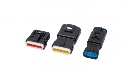
Figure 10: EDAC wire-to-wire inline connectors with an IP67 rating with double-latch options available for a high retention strength.
The connectors feature an IP67 ingress protection rating when mated that, according to the IEC 60529 standard, will entirely protect against dust as well as total immersion in water up to 1 meter. This ensures that no contaminants can penetrate the mate with both a wire seal and a housing seal as can be seen in Figure 11.
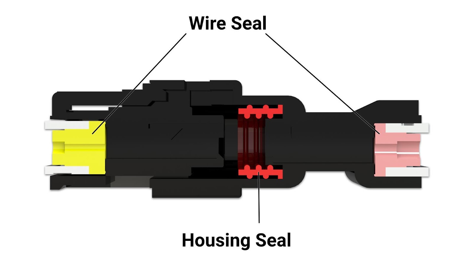
Figure 11: The seals within the inline connectors are pre-assembled into the housing so that external sealing is not required. For an unmated connector, waterproof caps are also available.
The double-latch technology on these connectors supports a high retention strength that has been proven (Figure 12). Tests performed with a Tensile Testing machine have shown that the double-latch technology supports retention strength of 10 kilogram-force (kgf) when being pulled at a rate of 25 mm/min.; this is 20% stronger than the single-latch alternatives. In a robotics application, this would help greatly when the connector heads are experiencing constant tensile forces and torsional strains that might cause the connector to disconnect.
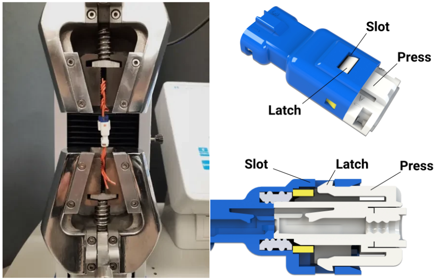
Figure 12: The EDAC inline connector’s double-latch system where plastic latches onto the top and bottom of the receptacle connector slide into the housing until they reach the slots (left). The retention test setup for the 560 series inline waterproof connectors (right).
Vibration tests were also performed on these connectors per MIL-STD-202G 201. The 560 series inline connectors were attached to three axes for two hours on each axis at 10Hz-55Hz-10Hz with a maximum amplitude of 1.52 mm. The tests revealed that the low-level contact resistance of the connectors was less than and equal to 8mΩ after the test ― well below the maximum contact resistance specified on the datasheet (15 mΩ). During the test, the sample also did not fall off, rupture, or damage, and the connector joint did not separate. This means that the connectors can also withstand constant vibration, this would be particularly useful for AMRs and AGVs that are rolling around rough terrain.
D-Sub Connectors
D-Sub connectors are used for serial, parallel port, and display communications. These connectors are used often to connect from the robot operating system to a processing unit such as a computer, microcontroller, or fpga for data (I/O) communication. These connectors can be ruggedized to ensure no failures will occur in harsh-environment applications. EDAC’s waterproof D-Sub connectors come with 9-, 15-, 25-, 26-, and 44-pin versions with a range of mounting options. The connectors are IP67 rated and are completely epoxy sealed using EDAC’s proprietary E-seal technology. The leads are potted in a mold, and a silicone o-ring is added for the waterproof rating (Figure 13).
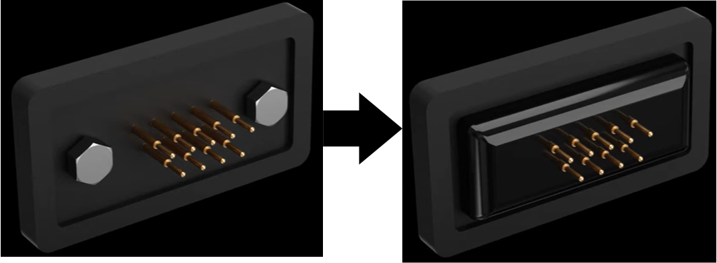
Figure 13: The seal used for the waterproof D-sub connectors limits the risk of epoxy wicking up leads and causing continuity issues.
The waterproof hood of the D-sub connectors includes strain relief, which is critical in cases where the cable assembly is continually mated on the robot as it is performing its allotted task and may experience constant flexure. For applications that do not require as much protection from contaminants and more EMI prevention, EDAC offers metal shells for the D-sub connectors that will provide additional grounding (Figure 14). Dust caps are also available with both waterproof and non-waterproof covers.
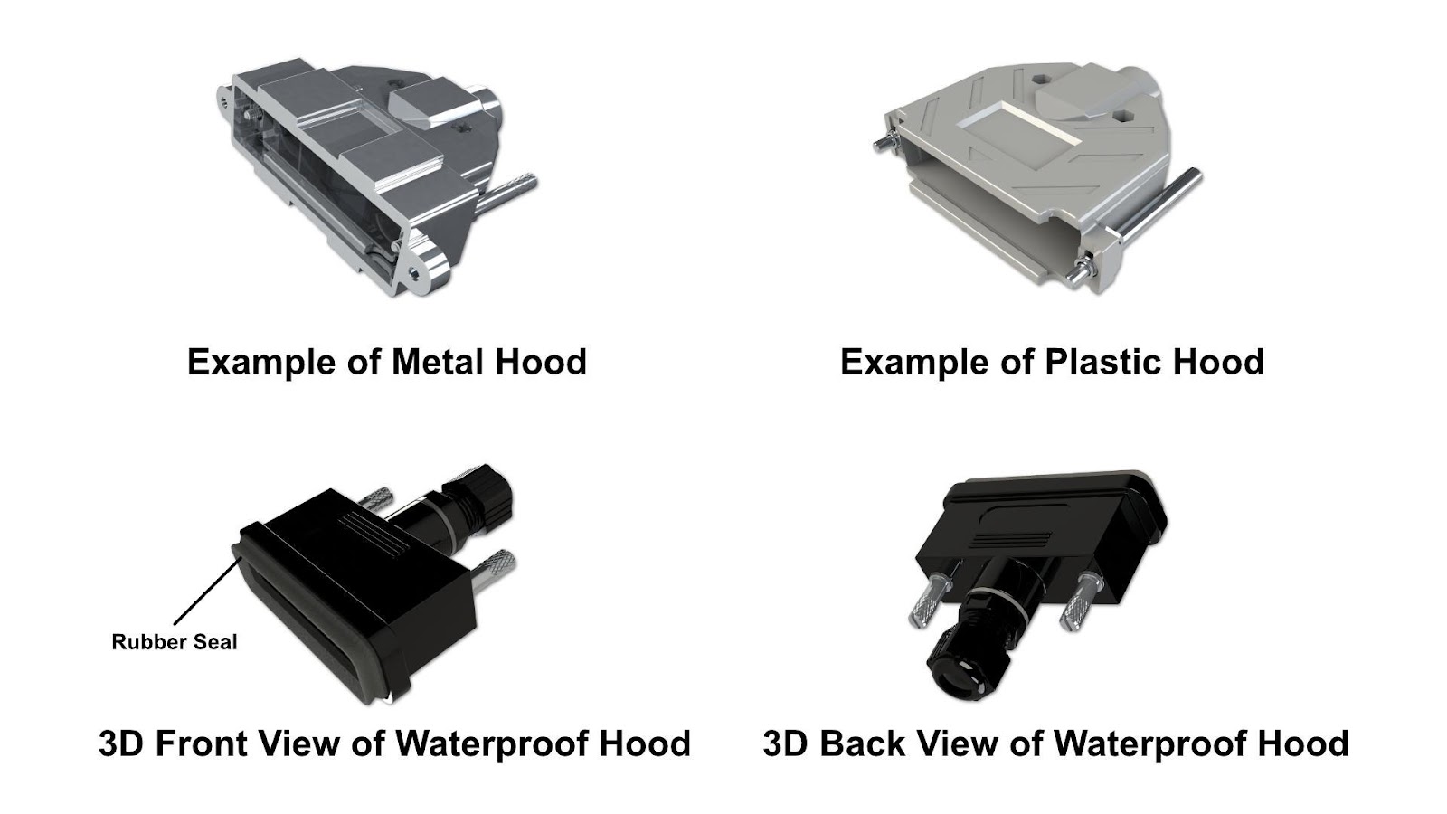
Figure 14: The hood offering for EDAC’s D-sub connectors.
Rectangular Connectors
Rectangular rack and panel connectors are a compact I/O solution for industrial robots and factory automation equipment (Figure 15). This is ideal for robots with a large amount of connections with up to 120 contact positions per connector. A high-integrity connection is maintained through their unique hermaphroditic contact design that incorporates a fork-like shape with beveled edges for a gas-tight connection with four points of contact. The chamfered edges also create a connection that floats in the insulator allowing for some movement of the contacts to compensate for the stacked tolerances of connectors with a large number of pins. This ensures that every pin within the connector head is mated and can endure the repetitive vibrational, torsional, and tensile forces of a robot. EDAC also offers MIL-C-28731 rectangular connectors for another layer of quality assurance.
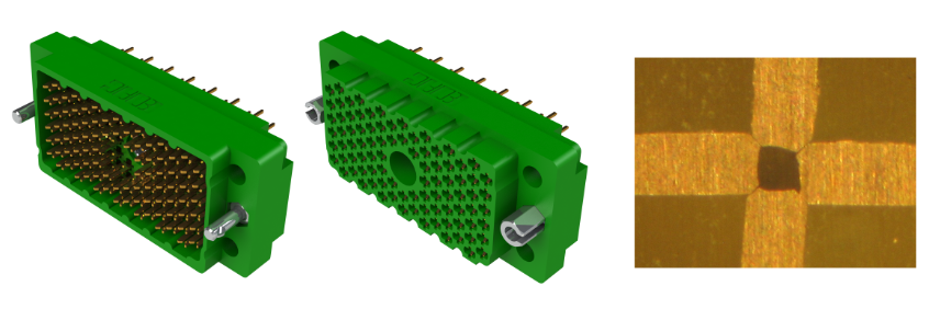
Figure 15: EDAC’s rectangular plug (left) and receptacle (middle) with hermaphroditic contacts. The beveled edge of the hermaphroditic contact allows for a high-continuity connection of the many contacts within the rectangular connector.
Rectangular connectors are available with metal covers with a removable side panel that includes strain relief. This allows for a degree of EMI protection and helps facilitate the ease of inspection and replacement of wiring in the field.
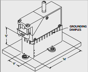
Figure 16: Optional metal cover with grounding dimples for the rectangular rack and panel connector to ensure the housing is connected to chassis ground to minimize EMI.
High-Speed Card Edge
Robots will use many different types of machine learning algorithms to assist them in their various tasks. Vision-guided robots will often use rugged computing platforms to assist with extreme processing capabilities and advanced servo and stepper motor controls. These embedded computers will use expandable card-edge-connected slots for high-speed protocols such as PCI/PCIe. Protocols such as these will allow for the robot to perform more complex tasks. In motion control applications, for instance, this enables movement through multiple axes in space with both linear and circular interpolations; this allows for machine tool movements that are both point-to-point with straight-line movements and continuous paths with contouring movements. Other use cases involve machine vision, where the PCIe-based edge accelerator allows the robot to process multiple 3D camera streams in near-real-time. There are PCIe expansion cards with CAN bus, ethernet, Fieldbus I/O, EtherCAT, DeviceNet, and other common industrial protocols to control and monitor all robot subsystems. The applications go on and on. High-speed card-edge connectors are necessary to accomplish these expansions. EDAC offers PCIe 3.0- and SAS 3.0-compliant card-edge connectors with differential pair signaling for a low-insertion loss in a dense package that conserves valuable board space (Figure 17). These high-speed protocols allow up to 21 Gbps of data transmission.
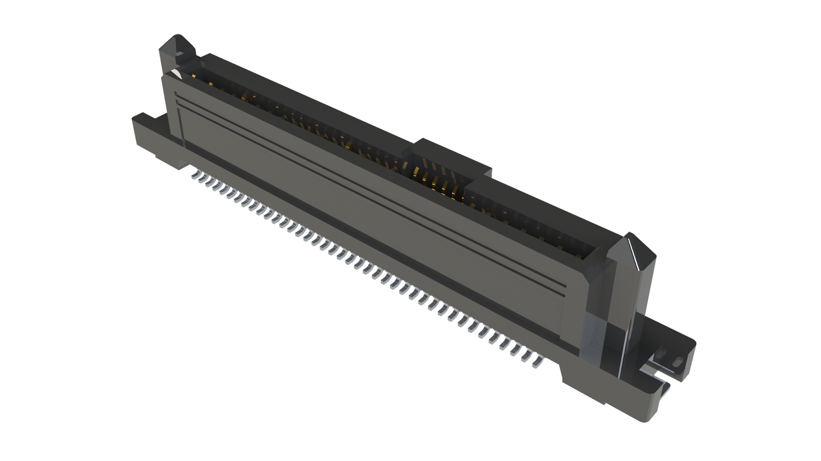
Figure 17: The 271 series of EDAC high-speed card-edge connectors that are both SAS 3.0 and PCIe 3.0-compliant with up to 68 contact positions.
Conclusion
Robots are utilized in almost every industry to assist with daily tasks at a high precision. These machines rely on power, data, and high-frequency signals to accomplish their intended goal. This quality and service life of the robot then ultimately depends on its electronic subsystems and connections. These can be subjected to some of the harshest conditions — from extreme temperatures and exposure to corrosive agents to cables that undergo constant mechanical stresses with both linear and rotational bends. All these strains must be considered when choosing the right connector for the task. EDAC offers a large portfolio of connectors that might be used within robotics. Each of these connectors has its type of ruggedization features that protect the connector (and cable) from the various stressors it might encounter in a robot.
This article is from EDAC Inc. and the original source could be found here: EDAC Robotic Interconnect Solutions
References
- User Guide for MiR100 Autonomous Mobile Robots. 2021. Available online: https://gibas.nl/wp-content/uploads/2021/01/ mir100-user-guide_31_en.pdf (accessed on 20 July 2022).
- Ramon, Manoel. “Assembling and Controlling a Robotic Arm.” Intel Galileo and Intel Galileo Gen 2 API Features and Arduino Projects for Linux Programmers, Apress, Berkeley, CA, 2014.
- Hunt, V. Daniel. Understanding Robotics. Academic Press, 1990.
- Lunine, J. I. (2008, May). Extreme Environments in the Solar System. Lunar and Planetary Institute Annual Meeting, May 2008, https://www.lpi.usra.edu/vexag/may2008/presentatio...
- Madariaga, R., Arevalo, L., Gabardi, T. et al. Advances in Robotic Tapping and Plugging of Non-Ferrous Smelting Furnaces: The MIRS Robotic Tapping Machine. JOM 74, 4009–4014 (2022). https://doi.org/10.1007/s11837-022-05446-2